Multi-Axis Goniometer For Retroreflectivity Standards Development At NIST
Dynamic Structures And Materials, LLC

Multi-Axis Goniometer For Retroreflectivity Standards Development At NIST by Dynamic Structures And Materials, LLC
Related Technologies:
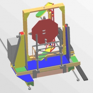
In order to resolve variations in the measurements of retroreflective road signs, pavement markings, and other traffic control devices and to establish industry standards, the National Institute of Standards and Technology (NIST) has established the Center for High-Accuracy Retroreflection Measurements. The heart of the new center is a dedicated reference instrument - a high-precision, six-axis goniometer designed by Dynamic Structures and Materials, LLC ("DSM") and installed at NIST's Gaithersburg, MD facility. The goniometer provides closed loop control of six independent degrees of freedom and travels 30m on a precision rail assembly. The system's robust design is large enough to accommodate actual road signs such as the octagonal STOP sign used in the U.S. (approximately 1 m diameter).
A 50m black tunnel houses the goniometer to eliminate stray illumination that could interfere with researchers' measurements. During experimentation, light is projected from a source (representing a headlight) onto a test object such as a road sign or pavement marking. The light is retroreflected to a photometer, which measures the amount of returning light (simulating what a vehicle's driver might see). Measurements in the facility are traceable to the candela, a SI unit maintained by NIST.
The specifications for high angular resolution and accuracy in the goniometer's operation resulted from the desire to use the equipment as a research instrument as well as a calibration device. Vertical deviation of the goniometer system's center over the 30m rail length is within ±0.75mm, and horizontal deviation of the center is within ±1.0mm. Final system specifications are tabulated below:
Axis of Motion Range of Motion Minimum Step Size Positioning Accuracy
X' (parallel to rail) ± 46 cm < 100 um < + 0.25 mm
Y (perpendicular to rail) ± 30.5 cm ± 10 um < + 0.050 mm
Z (vertical) ± 30.5 cm ± 10 um < + 0.050 mm
Pitch ± 95 deg 0.0002 deg <0.001 deg
Yaw ± 95 deg 0.0002 deg <0.001 deg
Epsilon ± 185 deg 0.0002 deg <0.001 deg
As part of the system's post-installation characterization, NIST determined that for any one axis move, the system's sphere of confusion is an ellipsoid of dimension 0.35 mm in the vertical direction and 0.12 mm in the horizontal direction.
Researchers at a remote PC control the motion of the system's axes through custom software written under National Instruments' LabWindows. MXI-3 technology, a PCI master/slave system, is used to couple the remote PC via a fiber optic data link running the length of the hallway to a National Instruments PXI-1002 chassis incorporated into the goniometer's structure. The PXI chassis also houses two NI PXI-7334 stepper motor motion cards and a NI PXI-8421/2 card to provide an interface for RS-485 communication with the system's 30m linear encoder.
DSM also incorporated an enclosure in the system's structure to protect the stepper motor drives and two NI UMI-7764 Universal Motion Interfaces. The UMI boxes provide connections for step and direction signals from the motion controllers to the stepper motor drives as well as connections for the majority of the position encoders. E-stop switches installed on the goniometer frame in easy reach of any bystander are routed to relays that disable power to the system's motors.
The accuracy of the goniometer's motion control system over such large motion ranges is made possible through the use of high-end motion components and sensors. Five-phase Oriental Motors Vexta Nanostep CFKII 569 stepping motors were chosen to produce precision motion for the three rotational axis of the goniometer, while two-phase Vexta CSK 268MAT stepping motors drive the linear axes of motion. When set at the smallest step angle, the five-phase Vexta stepper motors have 125,000 steps per revolution. DSM successfully coupled the stepper motors to high accuracy harmonic drives with a 160:1 gear reduction that yielded a potential resolution of greater than 20 million steps per revolution. Using rotary encoders to provide position feedback, actual “closed-loop” minimum step size for the three rotational axes was less than 0.0002 degrees or 1.8 million steps per revolution.
DSM selected HD Systems harmonic drive gear reducers to couple with the stepping motors. The harmonic drives provide a 160:1 single stage gear reduction in a very small package. The HD systems CSF-2UH gearheads have virtually zero backlash and come with built in roller bearings to support the output shaft. The HD harmonic drives provided dramatic increases in stepper motor holding torque to control the rotation of the large goniometer support frame with authority.
Each axis of the goniometer is monitored by an encoder and limit switches. The limit switches were incorporated into the frame to protect each axis against overtravel by disabling signals to the respective axis' motor. The encoders selected for the three rotary axes are from the Mercury 2000 family of high precision encoders from MicroE Systems, Inc. The optical encoders use glass-scales with interpolator electronics that enable up to 4.19 million counts per revolution. MicroE Systems precisely mounted the glass scales to DSM’s custom-designed encoder hubs. The encoders' small read heads were easily incorporated into the goniometer's structural design, and their robust tolerance to misalignment made adjustments during installation fast and simple.
This project was highlighted in the Spring 2004 Edition of PXI Technologies Review.
Go Back to Controls Sheeters
About Dynamic Structures And Materials, LLC

Dynamic Structures and Materials, LLC (DSM) specializes in electrical-mechanical design and prototyping services for challenging devices, machines, and systems. By partnering with industrial designers, engineers, and scientists, DSM’s varied expertise has enabled new and unique product development for industrial and consumer applications. DSM has extensive experience in motion control applications including micropositioning and nanopositioning system design using flexure-guided motion components. Specialty Motion System Competencies -------------------------------------------------- * Linear and rotary actuation systems for scanning applications, valves, and micro / nanopositioning equipment design * Flexure-guided mechanism designs for smooth motion * Piezoelectric and shape memory alloy materials Controls Software and Sensors -------------------------------------------------- * National Instruments LabVIEW VIs (CLAD certification), serial and USB communications, DLLs * HMI development * C, C++.net, VB.net, ASSEMBLY * Digital and analog sensor integration, data acquisition * Linear and non-linear control systems, including PID Electrical Circuit Design Capabilities -------------------------------------------------- * 50+ combined years of product design experience * Circuits for analog and power applications * Microcontroller and DSP implementations * Ultrasonic switching drivers for piezoelectric devices * Embedded systems software development Solid Modeling, Mechanical Design, FEA -------------------------------------------------- * 3D, 2D CAD * FEA-optimization of mechanisms and structures * Static, dynamic, modal, and transient analysis Precision Machine Design and Automation -------------------------------------------------- * Robotics, machine vision, laser scanning * Air bearing systems, harmonic drives, linear motors


